




 Home
Home
IEC
IEEE
ANSI
EN
IES-5302 Bay Control Unit
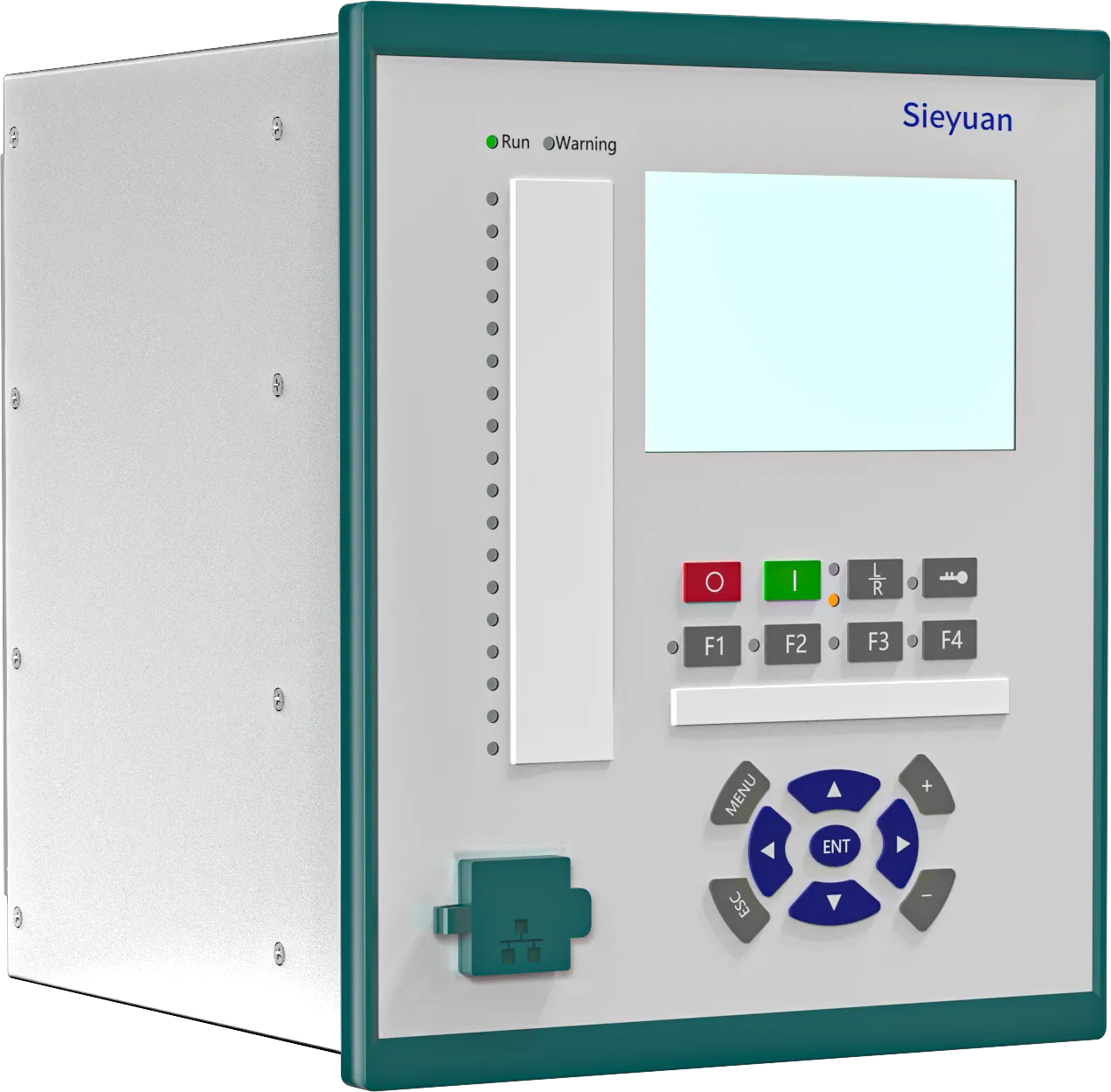
IES-5302 bay control unit is a general purpose control and automation device in all substations, powerplants and industrial domain applications. The modular conception permits the hardware adaption exact to client requirements. It adopts unified software and hardware platform, supports comprehensive functions including protection, control, measurement and monitoring, is easy to use and maintain. The device is freely programmable. Functional logic diagrams can be developed with the use of graphical programming tool which also supports the configuration of binary inputs and outputs, analog inputs, control buttons, LEDs, disturbance recorder, event recorder, and user interface. Freely programmable logic makes it possible to modify typical functional logic diagrams considering a peculiar nature of the protected object. Three basic types of standard 19”case help to choose the most appropriate solution.
-
Configurable to System Requirements
-
Engineered for Broad Deployment
-
Multi-Function Capability
-
Simplified Maintenance
Product Highlights

Configurable to System Requirements
Offers optional functions including voltage, current, power, and frequency protection, which form a complete backup protection. Supports DC analog input and DC analog output.

Engineered for Broad Deployment
Wide range of applications: It is suitable for a variety of application scenarios, and can be applied in single CB, dual CB, 3/2 whole diameter, multi-segment bus (maximum 4 segments), power transformer (2-windings, 3-windings or autotransformer), multi-bays (maximum 6 bays), IO-box, etc.
Multi-Function Capability
Support rich control functions, with optional functions as synchronization, reclosing, AVR, etc. HMI operation is simple and easy to use, providing single-line diagram display and control functions. Provide up to 15th harmonic measurement, as well as function of energy metering and power quality calculation.

Simplified Maintenance
Remote control, measurement, and other components are open to users for configuration. Each slot on the hardware can be assigned with I/O.
Technical Specification
Dimensions (WxHxD)
455 mm×266.7 mm×233.5 mm; (6U height, 1/1 chassis, excluding mounting bracket); 221.3 mm×266.7 mm×233.5 mm; (6U height, 1/2 chassis, excluding mounting bracket)
Mounting Way
Surface mounting, flush mounting, semi-flush mounting, wall mounting, and panel mounting
Material
Stainless stee
Protection Level(Front Panel)
IP54
Protection Level(Side Panel)
IP40
Protection Level(Rear Panel)
IP30
Communication Ports
2 or 4 100Base-TX RJ45 Ethernet ports; 2 or 4 100Base-FX optical ports; 2 RS-485 serial ports for SCADA communication; 1 RS-485 serial port for clock synchronization; 1 front RJ45 port for debugging
Clock Synchronization
IRIG-B; PPS; IEEE 1588; SNTP
Functions
CB/DS/ES Control; Tap position control; Measurement; Phase overcurrent protection (50/51P); Earth-fault protection (50/51G); Negative-sequence overcurrent protection (50/51Q); Switch Onto Fault Protection (SOTF); Phase overvoltage protection (59P); Positive-sequence overvoltage protection (59Pos); Negative-sequence overvoltage protection (59Q); Residual overvoltage protection (59G); Phase undervoltage protection (27P); Over-frequency protection (81O); Underfrequency protection (81U); Synchro check (25); Breaker failure protection (50BF); CB wear; Auto-reclosing (79)