


 Home


Power transformers are essential to modern electrical networks. They enable electricity to be transmitted at high voltages and converted to suitable voltage levels for substations, industrial facilities, and other applications. Choosing the right transformer requires an understanding of its operating principle, design options, cooling methods, electrical ratings, and testing requirements.
This guide explains the fundamentals of power transformers and outlines the key considerations for engineering and procurement decisions.
1. What Is a Power Transformer?
A power transformer is a static electrical device that transfers alternating-current (AC) electrical energy between circuits through electromagnetic induction, changing voltage levels without changing frequency. It enables efficient bulk power transmission and connects different voltage levels within electrical networks.
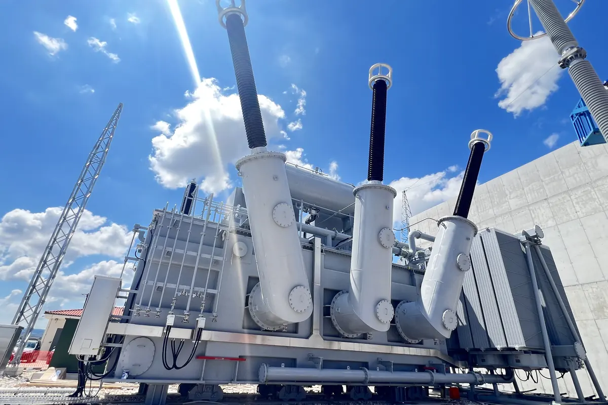
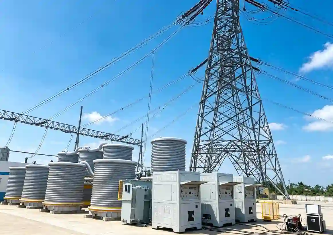
A liquid-immersed power transformer in service: the active part sits inside the tank, with bushings and cooling equipment mounted outside.
A typical liquid-immersed power transformer consists of the following main components:
Magnetic core: Provides a path for magnetic flux and is commonly constructed from laminated electrical steel.
Windings: Transfer electrical energy between circuits through electromagnetic induction.
Insulation system: Separates energized components and provides dielectric strength. Liquid-immersed designs commonly use solid insulation and insulating liquid.
Tap changer: Adjusts the effective turns ratio to support voltage regulation where required.
Bushings: Provide insulated electrical connections through the grounded enclosure.
Tank and cooling equipment: House the active part and help dissipate heat in liquid-immersed designs.
Protective devices: Monitor specified operating conditions and help detect abnormal conditions.
Component arrangements vary with transformer type, rating, insulation system, and application. Dry-type and gas-insulated designs, for example, use different insulation systems and enclosures.
2. How Does a Power Transformer Work?
A power transformer operates through electromagnetic induction. Alternating current in the primary winding produces a changing magnetic flux in the core, which induces an electromotive force in the secondary winding. In a conventional two-winding transformer, energy transfers magnetically between the windings without a direct electrical connection.
An ideal transformer’s voltage ratio is proportional to its winding turns ratio.
A transformer steps up voltage when the secondary winding has more turns than the primary winding, and steps down voltage when it has fewer turns.
In practice, some input energy is lost through core losses, winding resistance losses, and additional stray losses. For a given transmitted power, increasing transmission voltage reduces current and helps limit resistive losses in transmission lines. This makes power transformers essential for efficient electricity transmission and voltage conversion.
3. Types of Power Transformers
Power transformers can be classified by insulating medium, winding configuration, and installation or deployment arrangement. These categories describe different design characteristics and may overlap. The following tables introduce representative types covered by Sieyuan Electric's product portfolio.
3.1 By Insulating Medium
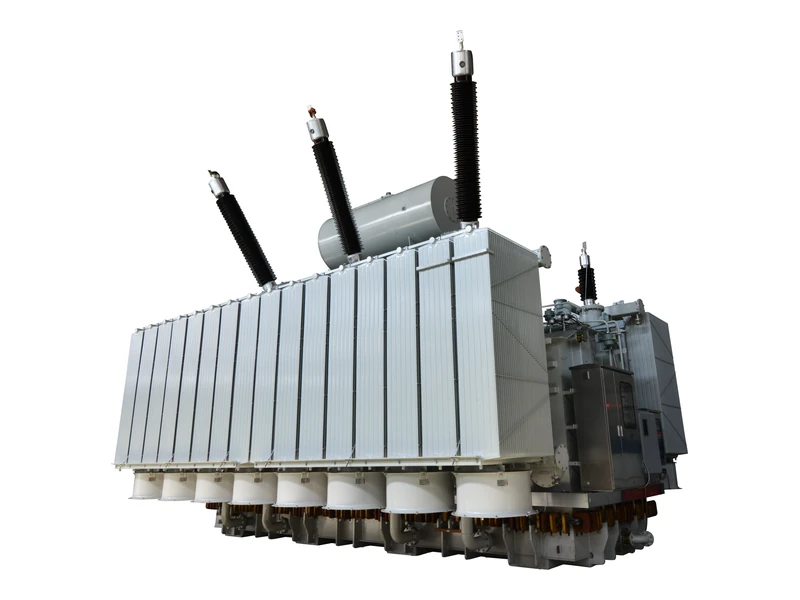
Mineral oil-immersed transformer
Uses mineral oil for electrical insulation and heat transfer.
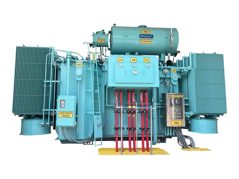
Natural ester liquid-immersed transformer
Uses plant-derived ester fluid, which generally offers a higher fire point and favorable biodegradability compared with conventional mineral oil.
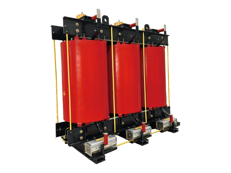
Dry-type transformer
Uses air and solid insulation rather than liquid-immersed windings. Designs include cast-resin configurations.
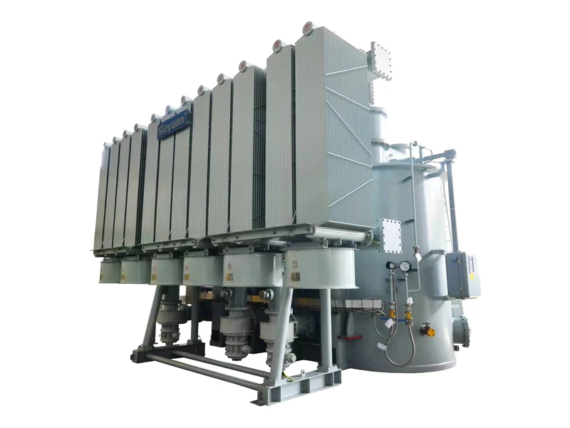
Gas-insulated transformer(GIT)
Uses a gaseous insulating medium in a specially designed insulation system or enclosure.
3.2 By Winding Configuration
Two-winding transformer
Two-winding transformers have two electrically distinct windings, typically a primary winding and a secondary winding. Electrical energy is transferred between the windings through electromagnetic induction, without a direct electrical connection between them.
Three-winding transformer
Three-winding transformers have three electrically distinct windings on a common magnetic core. The windings can be configured to connect three voltage levels or circuits, depending on the transformer design.
Autotransformer
Autotransformers use a common winding section shared by the input and output circuits. Compared with conventional two-winding transformers of comparable ratings, they can require less conductor material and occupy less space under suitable design conditions. However, they do not provide galvanic isolation between the input and output circuits.
Split-winding transformer
Split-winding transformers feature a winding divided into separate sections on a common magnetic core. A typical configuration includes one high-voltage winding and two or more secondary winding sections. Depending on the winding arrangement and leakage impedance, this configuration can help limit fault-current transfer between secondary circuits.
3.3 By Installation and Deployment
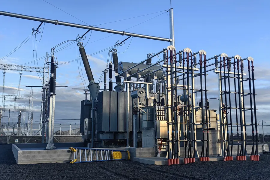
Fixed transformer
Installed at a designated location and designed for indoor or outdoor installation.
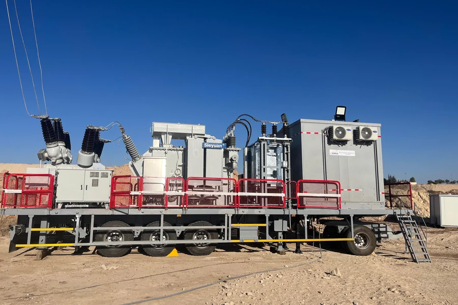
Mobile substation transformer
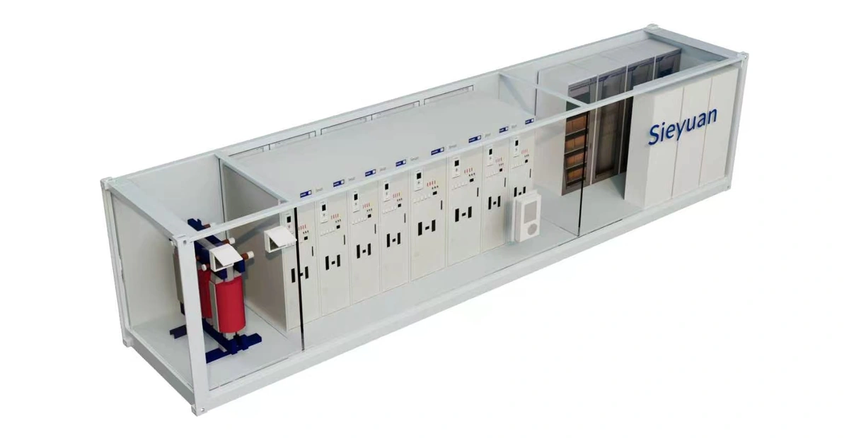
Designed for transport and deployment as part of a mobile substation; may be mounted on a trailer, skid, or other transportable platform.
Actual specifications and application suitability depend on the selected product and project requirements.
4. Transformer Cooling Methods Compared
Power transformers generate heat through winding losses, core losses, and additional stray losses. Effective cooling helps control temperature, limit insulation aging, and maintain the specified rated capacity.
For liquid-immersed transformers, common cooling designations include ONAN, ONAF, OFAF, ODAF, OFWF, and ODWF.
| Cooling Method | Oil Circulation | External Cooling | Key Characteristics |
|---|---|---|---|
| ONAN | Natural | Natural air | Oil circulates by convection, while surrounding air removes heat from radiators. A relatively simple arrangement without oil pumps or cooling fans. |
| ONAF | Natural | Forced air | Fans blow air across radiators to increase heat dissipation without mechanical oil circulation. |
| OFAF | Forced | Forced air | Oil pumps circulate oil through the cooling system, while fans enhance heat rejection. |
| ODAF | Forced and directed | Forced air | Forced oil circulation with directed oil flow through designated winding cooling channels, combined with forced-air cooling. |
| OFWF | Forced | Forced water | Oil circulates through oil-to-water heat exchangers, while a separate water circuit removes heat. Suitable where appropriate cooling-water infrastructure is available. |
| ODWF | Forced and directed | Forced water | Forced oil circulation with directed oil flow through designated winding cooling channels, combined with forced-water cooling via oil-to-water heat exchangers. It delivers superior heat dissipation and is commonly adopted for large GSU transformers and hydropower projects with reliable cooling water supply. |
The appropriate cooling method depends on transformer design and rating, loading profile, ambient conditions, installation space, and project requirements. Forced cooling can increase heat dissipation, but actual capacity depends on the complete thermal design.
For OFWF and ODWF systems, water quality, leakage monitoring, heat-exchanger maintenance, and prevention of water ingress into the insulating system are important design considerations.
5. Where Are Power Transformers Used?
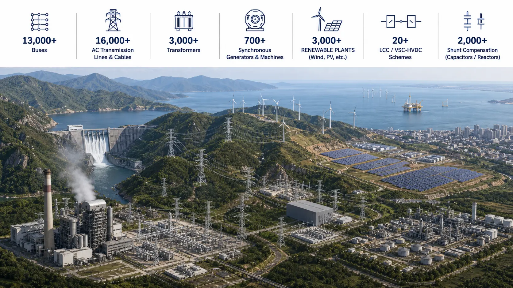
Power transformers are used across a wide range of power generation, transmission and distribution, industrial, and infrastructure applications. Their configurations and technical requirements vary according to the electrical system and operating environment.
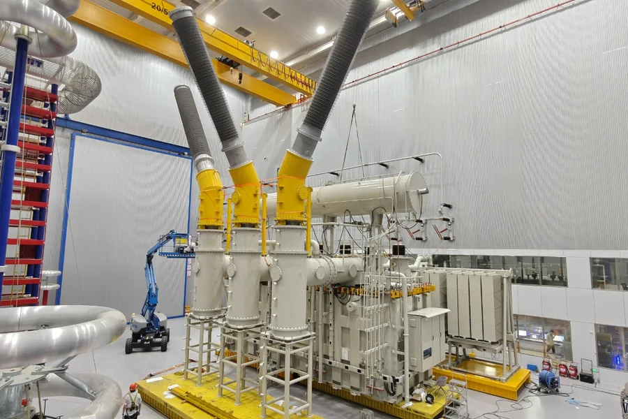
Power generation
Generator step-up (GSU) transformers increase generator output voltage for connection to the power grid. They are used in conventional power plants and other electricity generation facilities.
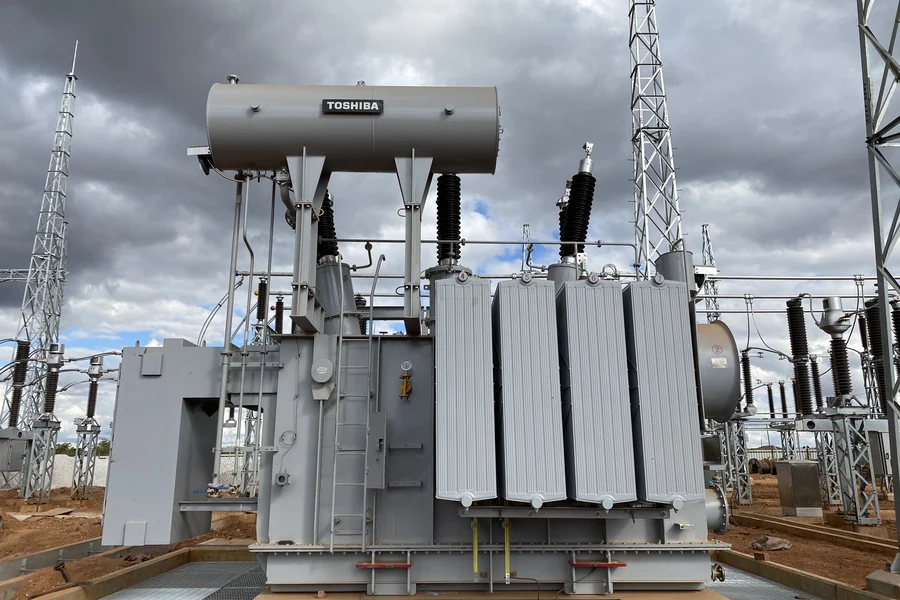
Transmission and distribution
Power transformers connect different voltage levels within transmission and distribution networks. They enable electricity to be transferred from high-voltage transmission systems to lower-voltage networks for further distribution.
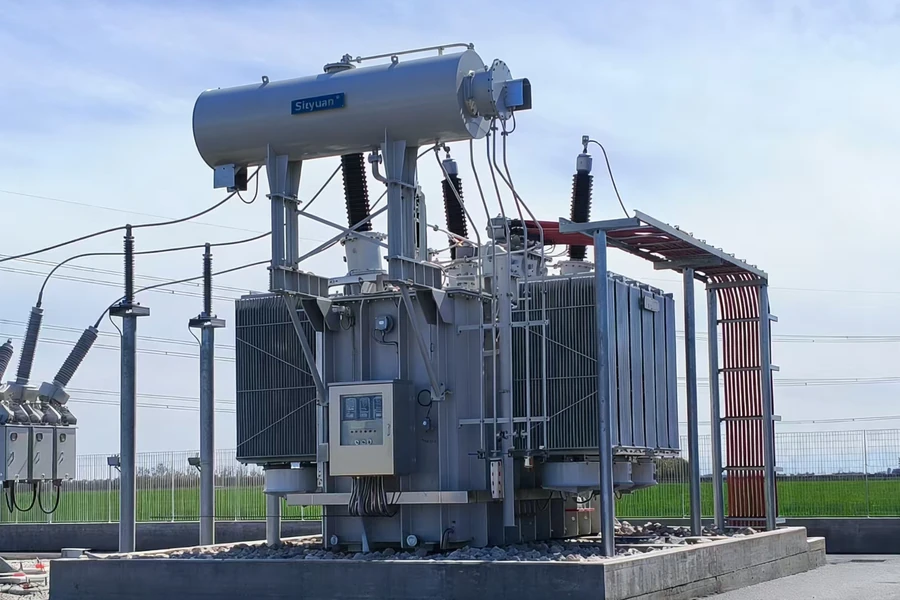
Renewable energy
Transformers connect solar photovoltaic (PV) plants, wind farms, and other renewable energy installations to collection networks or the utility grid, enabling generated electricity to be integrated into the wider power system.
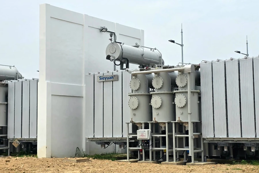
Energy storage systems
In battery energy storage systems (BESS), transformers connect power conversion systems to medium-voltage or high-voltage networks. They support power exchange between the battery system and the grid, including charging and discharging.
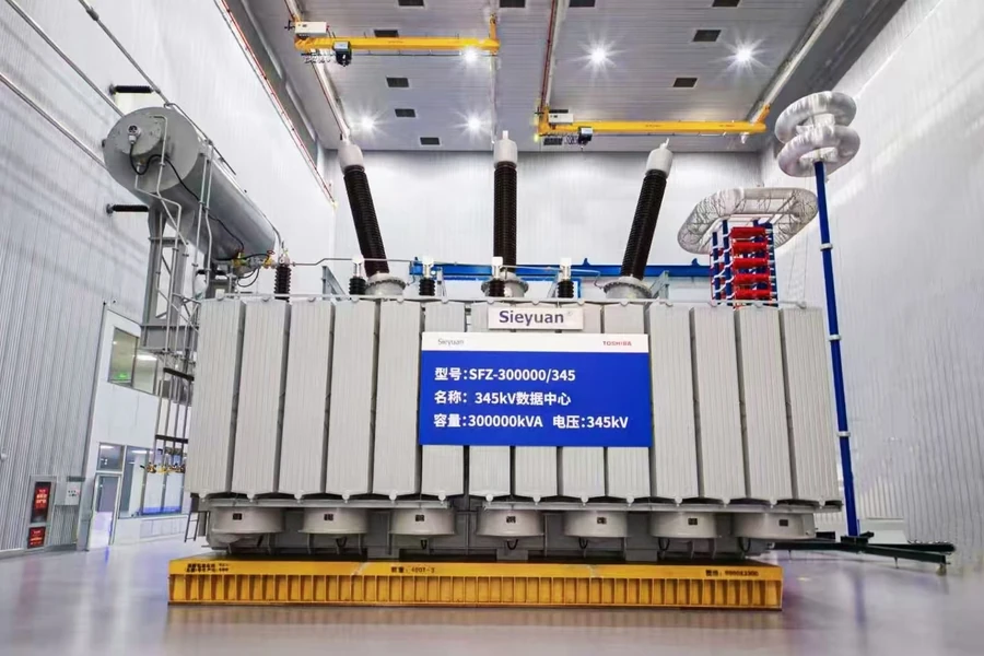
Data centers and commercial facilities
Transformers supply and distribute electrical power within data centers, large commercial buildings, and other facilities with substantial electricity demands. They form part of the electrical infrastructure supporting IT equipment, building services, and other loads.
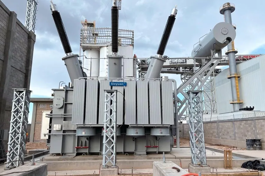
Mining, manufacturing and heavy industry
Industrial transformers supply power to mining operations, steel plants, manufacturing facilities, and other energy-intensive industrial processes. They support the operation of production equipment, large motors, and industrial drive systems.
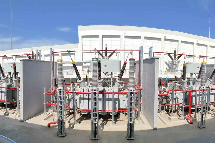
Oil, gas and petrochemical facilities
Transformers supply electrical power to refineries, natural gas processing plants, and petrochemical facilities. They support the electrical systems used in processing operations and associated plant infrastructure.
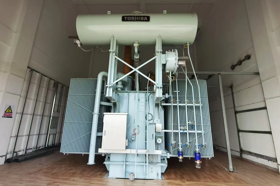
Railways and transportation infrastructure
Transformers are used in railway traction power supply systems and auxiliary power networks. Their functions vary with the railway electrification system and may include supplying traction power or supporting station and infrastructure loads.
These examples illustrate common applications of power transformers across the power sector, industry, and infrastructure. Specific transformer configurations depend on the requirements of each application and electrical system.
6. How to Select a Power Transformer
Selecting a power transformer requires a coordinated assessment of electrical ratings, load requirements, operating conditions, grid compatibility, and lifecycle costs. The following factors provide a framework for preliminary engineering and procurement specifications.
6.1 Voltage Rating and Network Position
Determine the required primary and secondary rated voltages according to the transformer's position in the electrical network. Distinguish the system nominal voltage from the transformer's rated voltage and, where applicable, the highest voltage for equipment.
Insulation coordination requirements, including lightning impulse withstand levels, switching impulse requirements where applicable, and power-frequency withstand requirements, should be specified in accordance with the applicable standards and system conditions. IEEE-based specifications may use the term Basic Impulse Level (BIL), while IEC-based specifications commonly refer to rated insulation levels and associated impulse withstand requirements.
6.2 Load Profile and Capacity Planning
Select the rated power in MVA based on expected continuous demand, peak loading, load cycles, future expansion, and applicable overload requirements. Motor starting, nonlinear loads, renewable generation variability, and other transient operating conditions may also affect capacity planning.
Cooling stages such as ONAN and ONAF may provide different rated capacities when the transformer is designed and rated for those stages. Overload capability should be assessed against applicable loading guidance, thermal conditions, insulation-aging considerations, and manufacturer data.
Once capacity requirements are established, confirm the winding configuration, vector group, neutral grounding arrangement, and parallel-operation requirements to ensure compatibility with the electrical system and intended operating conditions.
6.3 Lifecycle Cost and Efficiency
Transformer selection should consider total cost of ownership (TCO), rather than initial purchase price alone.
No-load losses: Occur whenever the transformer is energized and are primarily associated with magnetic losses in the core.
Load losses: Vary with load current and include winding resistance losses and additional stray losses.
For long-life assets, the cost of losses over the expected service life can significantly affect the economic comparison between designs. The assessment should account for expected loading, electricity prices, loss evaluation factors, maintenance costs, cooling-system energy consumption, and assumed service life.
A higher initial purchase price may be justified by lower lifetime operating costs, depending on the transformer's loss characteristics and the project's operating profile.
6.4 Site and Climate Factors
Evaluate ambient temperature, altitude, seismic requirements, humidity, pollution, coastal exposure, chemical contamination, acoustic limits, and available installation space.
High-altitude installations may require adjustments to external insulation clearances, cooling design, or rated performance, depending on applicable standards and site conditions. Coastal and industrial environments may require additional corrosion protection, while indoor or densely populated locations may impose stricter fire-safety and noise requirements.
Transportation access, lifting constraints, maintenance clearances, and cooling-equipment layout should also be considered to support practical installation and long-term maintenance.
6.5 Grid Stability and Loading
Transformer impedance, winding configuration, and grounding arrangements affect fault-current levels, voltage regulation, and parallel operation. Short-circuit impedance should be selected in coordination with system studies, balancing fault-current limitation against voltage drop, losses, and other operating requirements.
Where inverter-based renewable generation, railway systems, or other nonlinear loads are connected, harmonic currents and their thermal effects should be evaluated. Switching transients, short-circuit stresses, and protection coordination should also be assessed to ensure the transformer is compatible with the grid's operating and fault conditions.
7. Transformer Testing and Standards
Power transformer testing verifies electrical performance, dielectric integrity, thermal design, and mechanical robustness. Under the IEC 60076 series, tests are generally classified as routine tests, type tests, and special tests. The applicable test scope depends on transformer design, relevant standards, purchaser requirements, and contractual specifications.
| Test Category | Purpose | Examples |
|---|---|---|
| Routine Tests | Verify manufacturing quality and specified performance for each individual transformer. | Winding resistance measurement, voltage ratio measurement at all tap positions, phase displacement measurement, insulation resistance measurement where specified, separate-source AC withstand voltage testing, induced AC overvoltage testing, no-load loss and load loss measurements, and short-circuit impedance measurement. |
| Type Tests | Demonstrate that a representative design meets specified performance requirements. | Temperature-rise testing to verify the thermal performance of the transformer and its cooling system under specified test conditions; lightning impulse (LI) withstand testing to assess insulation withstand capability against transient overvoltages; and other applicable tests required by the relevant standard. |
| Special Tests | Assess additional characteristics required by standards, purchasers, or project specifications. | Short-circuit withstand testing to assess the transformer's mechanical capability to withstand electromagnetic forces under short-circuit conditions; acoustic sound level measurement; partial discharge measurement where applicable; and frequency response analysis (FRA). |
The exact test list and classification depend on the applicable parts of IEC 60076 or other governing standards and the purchase specification. Not every test is mandatory for every transformer.
For procurement, buyers should confirm the required test scope, acceptance criteria, witness or hold points, and documentation requirements before manufacturing begins.
8. Power Transformer Solutions from Sieyuan Electric
Power transformer selection depends on voltage ratings, capacity requirements, operating conditions, installation constraints, and grid compatibility. Sieyuan Electric offers power transformer solutions for utility, renewable energy, and industrial applications, with a portfolio covering different transformer types and deployment needs.
Representative product capabilities include:
Oil-immersed power transformers:
Rated up to 1250 MVA / 765 kV.
Natural ester liquid-immersed transformers:
Rated up to 400 MVA / 500 kV.
Gas-insulated transformers (GIT):
Rated at 75 MVA / 220 kV.
Mobile transformers:
Rated up to 100 MVA / 220 kV.
Actual ratings, configurations, and application suitability depend on the specific product design and project requirements. Refer to the relevant product specifications or technical documentation to confirm the applicable parameters.
For further information, consult Sieyuan Electric's relevant power transformer product pages and technical documentation.